


Left-hand rule, right-hand rule, right-hand screw rule. The left-hand rule, this is the basis for the analysis of the force of the motor rotation. Simply put, it is the current-carrying conductor in the magnetic field, which will be affected by the force.
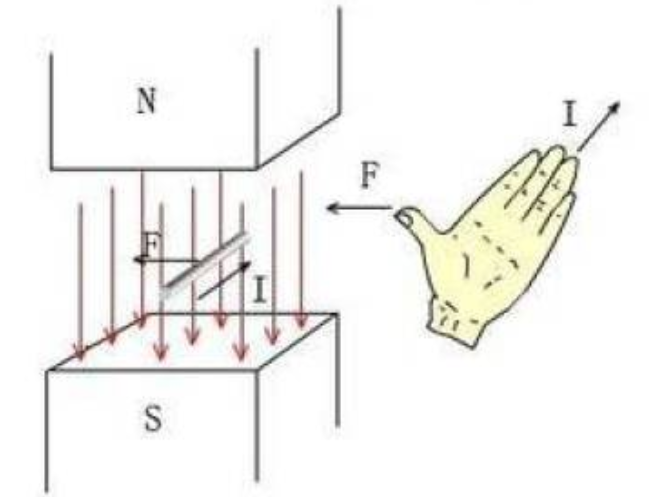
Let the magnetic field line pass through the front of the palm, the direction of the fingers is the direction of the current, and the direction of the thumb is the direction of the magnetic force. The traction of the force cuts the magnetic field lines to generate electromotive force.
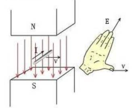
Let the magnetic field line pass through the palm, the direction of the thumb is the direction of motion, and the direction of the finger is the direction of the generated electromotive force. Why talk about induced electromotive force? I don’t know if you have any similar experience. When you combine the three-phase wires of the motor and turn the motor by hand, you will find that the resistance is very large. This is because the induction occurs during the rotation of the motor. The electromotive force generates current, and the current flowing through the conductor in the magnetic field will generate a force opposite to the direction of rotation, and everyone will feel that there is a lot of resistance to rotation.
The three-phase wires are separated and the motor can be turned easily
The three-phase lines are combined, and the resistance of the motor is very large. According to the right-hand screw rule, hold the energized solenoid with the right hand, so that the four fingers are bent in the same direction as the current, then the end pointed by the thumb is the N pole of the energized solenoid.
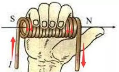
This rule is the basis for judging the polarity of the energized coil, and the direction of the red arrow is the current direction. After reading the three rules, let’s take a look at the basic principles of motor rotation. The first part: DC motor model We find a model of a DC motor that has been studied in high school physics, and conduct a simple analysis through the magnetic circuit analysis method.
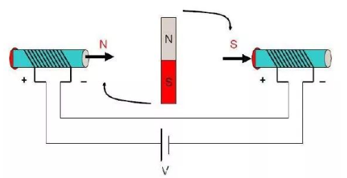
State 1 When current is applied to the coils at both ends, according to the right-hand screw rule, an applied magnetic induction intensity B (as shown by the thick arrow) will be generated, and the rotor in the middle will try to make the direction of its internal magnetic induction line as far as possible. The direction of the outer magnetic field line is consistent to form a shortest closed magnetic field line loop, so that the inner rotor will rotate clockwise. When the direction of the rotor magnetic field is perpendicular to the direction of the external magnetic field, the rotational torque of the rotor is the largest. Note that the “moment” is said to be the largest, not the “force”. It is true that when the rotor magnetic field is in the same direction as the external magnetic field, the magnetic force on the rotor is the largest, but at this time the rotor is in a horizontal state and the force arm is 0, and of course it will not rotate. To add, the moment is the product of the force and the force arm. If one of them is zero, the product is zero. When the rotor turns to the horizontal position, although it is no longer affected by the rotational torque, it will continue to rotate clockwise due to inertia. At this time, if the current direction of the two solenoids is changed, as shown in the figure below, the rotor will continue to rotate. turn forward clockwise,
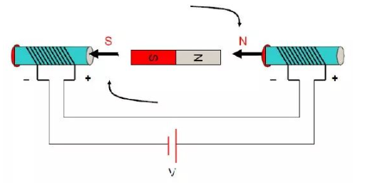
In state 2, the current direction of the two solenoids is constantly changed, and the inner rotor will continue to rotate. This action of changing the direction of the current is called commutation. A side note: When to commutate is only related to the position of the rotor and not directly related to any other quantity. Part 2: Three-phase two-pole inner rotor motor Generally speaking, the three-phase windings of the stator have star connection mode and delta connection mode, and “two-two conduction mode of three-phase star connection” is the most commonly used, which is used here. This model is used for a simple analysis.
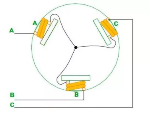
The figure above shows how the stator windings are connected (the rotor is not shown as a hypothetical two-pole magnet), and the three windings are connected together in a “Y” shape through the central connection point. The whole motor leads to three wires A, B, C. When they are energized two by two, there are 6 cases, namely AB, AC, BC, BA, CA, CB. Note that this is in order.
Now I look at the first stage: AB phase is energized
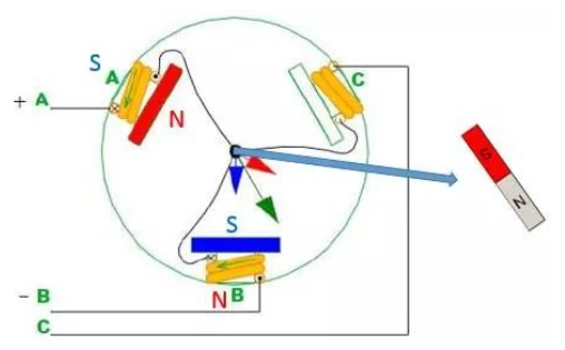
When the AB phase is energized, the direction of the magnetic field line generated by the A pole coil is shown by the red arrow, and the direction of the magnetic field line generated by the B pole is shown by the blue arrow, then the direction of the resultant force is shown by the green arrow, then Assuming that there is a two-pole magnet, the N-pole direction will coincide with the direction shown by the green arrow according to “the rotor in the middle will try to keep the direction of its internal magnetic field lines consistent with the direction of the external magnetic field lines”. As for C, he has nothing to do with him for the time being.
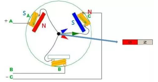
Stage 2: AC Phase Energized
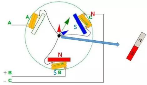
The third stage: BC phase electrification
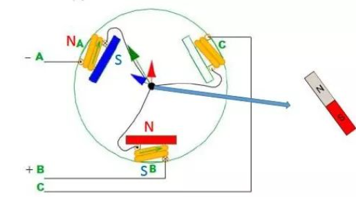
The third stage: BA phase is energized
The following is the state diagram of the intermediate magnet (rotor):Each process rotor rotates 60 degrees
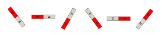
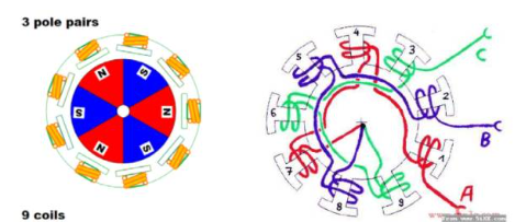
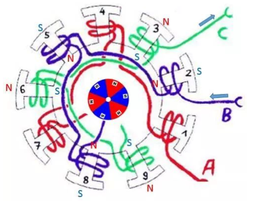
The complete rotation is completed in six processes, of which six commutations are made. The third part: three-phase multi-winding multi-pole inner rotor motor Let’s look at a more complicated point. Figure (a) is a three-phase nine-winding six-pole (three-phase, nine-winding, six-pole) motor. Opposite pole) inner rotor motor, its winding connection is shown in figure (b). It can be seen from Figure (b) that the three-phase windings are also connected together at the intermediate point, which is also a star connection. Generally speaking, the number of windings of the motor is inconsistent with the number of permanent magnet poles (for example, 9 windings and 6 poles are used instead of 6 windings and 6 poles), so as to prevent the teeth of the stator and the magnets of the rotor from attracting and aligning.
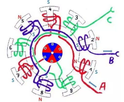
The principle of its motion is: the N pole of the rotor and the S pole of the energized winding have a tendency to align, and the S pole of the rotor and the N pole of the energized winding have a tendency to align. That is, S and N attract each other. Note that it is different from the previous analysis method. Well, let’s help you analyze it again. The first stage: AB phase is electrified
Stage 2: AC Phase Energized
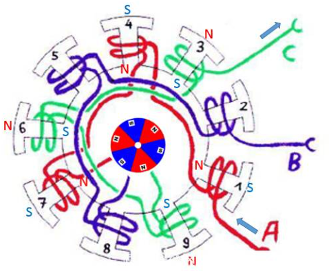
The third stage: BC phase electrification
Post time: Oct-21-2022